Update 2017-08-19: Updated Links, linked to follow on parts
Previous Parts
First of all, if you're reading this I assume you've completed Part 1 and Part 2. In the last part we covered what the logic might look like. I assume you've built your python scripts and FPGA logic in such a way that you can now readout a device where the firmware is unlocked. You have logic capable of generating glitch pulses of varying widths with varying delays, but have yet to glitch the target.
The Logic
So I published my logic to the Toothless Github, so you can grab a copy here. This Project contains both the python script as well as the necessary Verilog. Here I'm just going to outline the Verilog as it was last week's TODO.
- cmd module - The
cmdmodule is responsible for recieving commands from the host. It is realized as a state machine that can distinguish from variable length data in the format<length><data>and fixed length commands to the FPGA in the format<\x00><cmd>, as well as writes to the FPGA registers in the format<\x00><register><data> - resetter module - The
resettermodule simply holds the line low for enough clock cycles for the LPC1343 target board to fully reset. - delay module - The
delaymodule is a simple 2-state FSM that simply counts to realize a delay. - trigger moudle - The
triggermodule consists of a simple 2-state state machine that checks therdyof thedelaymodule after aboard_rsthas occurred. Once the delay module has finished, i.e.rdyis high, it set it's outputvalid. - pulse module - The
pulsemodule is a simple 2-state FSM that simply counts to realize the pulse width and it also has an additional counter for how many times this should be repeated. This configuration makes it easy to create pulses of arbitrary width.
Some hardware hacking equipment required
People always ask me what lab equipment to buy, so I started a spreadsheet. https://t.co/ZsPpH9z1FL
— Dmitry Nedospasov (@nedos) August 14, 2017
I started to put together a Recommended Lab Equipment. Lab Equipment turned out to be such a popular topic, I'm certain I will revisit it regularly. The question I always get is "what's the difference?" or "why can't I buy the cheap Chinese version?". What you're paying for when you buy good lab equipment is confidence - confidence it's working as it should. For example, when you're buying a multimeter you want to be sure it will warn you that the battery is low instead of giving you false measurements. You want to be confident that if you turn the range switch, it won't explode. When it comes to power supplies, you want them to output voltages accurately and clamp over currents quickly. You don't want them to overshoot the voltage, potentially damaging your circuit.
The good news with good lab equipment is, you only buy it once and it'll serve you for many, many years. So if anything consider it an investment in yourself. However, I'll readily admit that a balance has to be struck in terms of the money you're shelling out and when. One of the problems I see the most with companies is a lack of sufficient equipment. For example if you have 6 engineers, 1 good multimeter is not enough. That's what I tried to highlight with my list. If you're a company, you'll want to eventually have multiple multimeters, power supplies, logic analyzers and oscilloscopes. If you're just funding you're own hobby/interest than the story is a bit different. I promise, I'll go over some of my favorite lab equipment, but in the mean time I highly recommend you check out some of Dave Jones' reviews on Youtube.
Necessary Electronics
At the very least, you'll need the following electronics:
- Maxim Max4619 (Analog multiplexer), get it on on Digikey.
- A cheap breadboard, or splurge and get a 3M breadboard.
- Jumper wires, even though the breadboard will probably include some, you can't have enough of these. Just like no one crimps their own ethernet cables in 2017 - don't crimp your own jumper wires!
- Set of capacitors (optional, but recommended), ideally containing 1uF, 10uF and 47uF (these are the most common values, you'll use for prototyping). Use these to bypass the Max4619 on the breadboard.
Recommended Lab Equipment
I strongly recommend you grab a couple items from the list to make debugging your circuit much easier.
- Multimeter - I always say that the first piece of equipment worth investing in is a decent multimeter. I personally recommend the Fluke 117. The Fluke will serve you many years and it is excellent in everything it does. You can also consider getting something cheaper like an Extech EX330, for example.
- Oscilloscope (optional) - Whenever working with waveforms, you'll want an oscilloscope. In particular when we're talking about analog wave forms. You might just see a flat line on a logic analyzer.
- Lab Power Supply - If you don't have one yet, I recommend you get a cheap 3-channel power supply. Why 3-channels? We'll be supplying a voltage to the rest of the board (3.3V), we'll want a low operating voltage (1.5V-1.6V) and a glitch voltage (0V-0.6V). One 3-channel power supply is always nice to have. If you really want to save some money, you could power the 3.3V for the board from the FPGA and simply supply the low operating voltage and glitch to ground, i.e. 0V. If that's the case, you can get by with just a single channel power supply. Consider picking up something like this lab supply or if you don't mind modifying an old wall wart, you can go for one of these guys and simply step the voltage down. If you really don't mind spending the extra money and buying the only power supply you'll ever need, buy a Rigol DP832.
Soldering Equipment
For the modifications we'll be doing you won't need anything special. Even a cheap soldering iron will probably do, but if you don't yet own a soldering station, now would be a good time to get one. You can take a look at my recommended equipment list and hop over to the Soldering Equipment tab. If you just want a good a starter soldering station, consider getting the Hakko FX888D.
Modifying the target
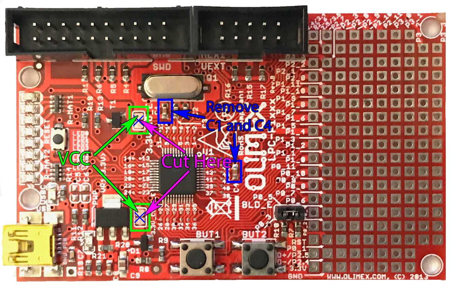
To glitch the target we'll need to disconnect the microcontroller from all of the bypass capacitors and supply circuitry as these all have some capacitance, which will effectively filter the glitch. One option would be to take the microcontrolelr, desolder it and solder it back onto a breakout board. However, that's too much work, so it's easier just to modify the Olimex P1343 development board. I annotated the necessary modifications in the image below.

Here's a quick run down for clarity:
- Remove the decoupling capacitors C1 and C4.
- Disconnect the microcontroller from the supply. The microcontroller is connected via 2 pins to the supply, so we'll have to cut two wires on the PCB. Fortunately on this development board, it's really easy. We simply need to cut through the wire running between the two pads of the
3.3V_CORE_Efootprint and the3.3V_CORE_IO_Efootprint, respectively. I recommend using a scalpel or knife. Verify that there is no connection between each of the two pads using the continuity test on your multimeter. - Finally cut one end of a jumper wire, leaving a male connector on the other side. We'll use the male connector to connect to female headers on the Digilent Arty FPGA board. Now strip the wire and solder it to the VCC pads of
3.3V_CORE_Eand3.3V_CORE_IO_E.
The final result will look something like this (I'll try to upload a nicer image when I get back home):

Connecting the Max4619 on the Breadboard
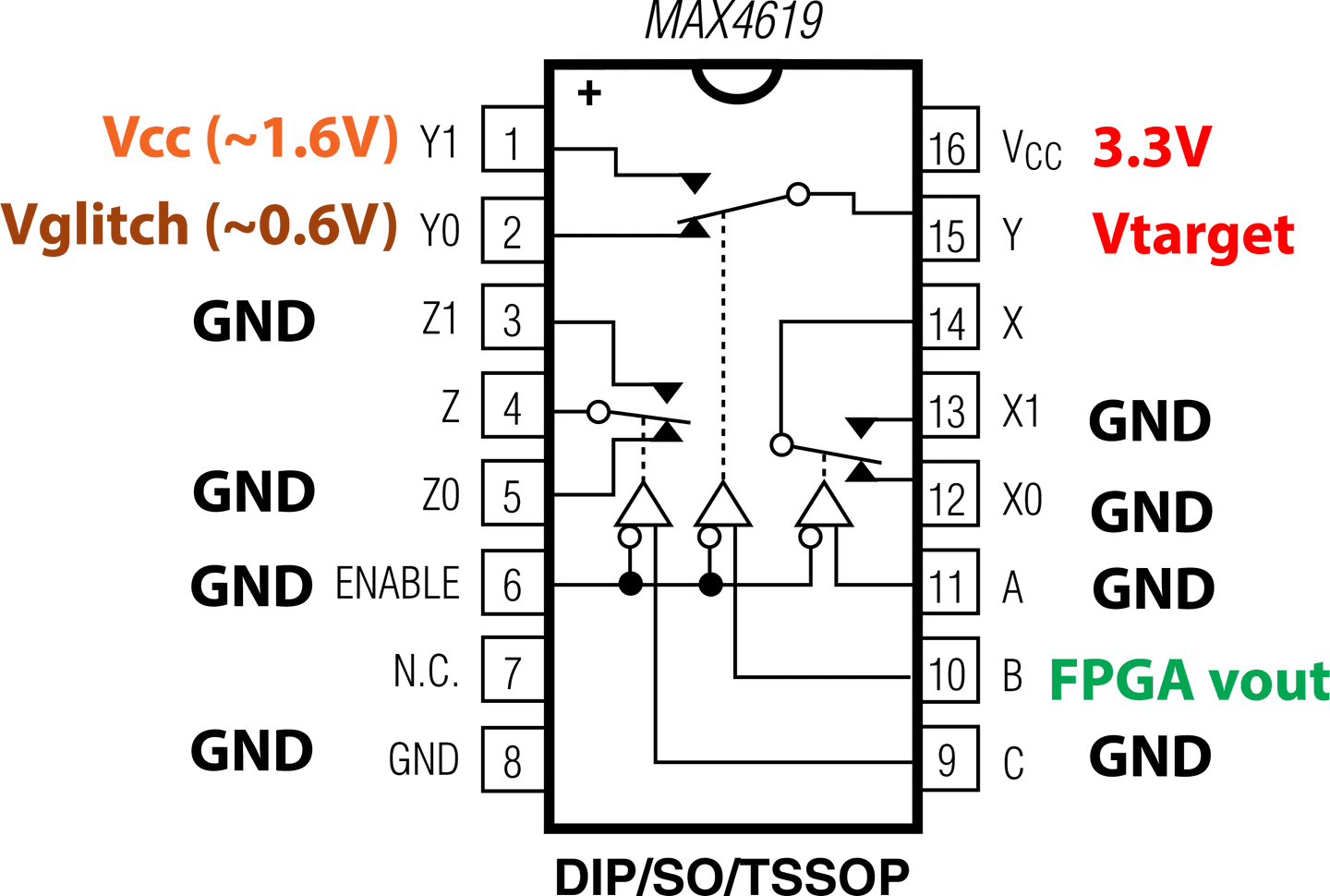
Whenever you work with a power supply, always set a current limit. A reasonable current limit for our applications is 200mA or 0.2A. That's already way more than we will end up using. Next, when connecting the Max4619 there's a couple of gotchas if you're not used to working with these kinds of devices. First of all, the enable is active low, meaning you must tie it to ground for anything to happen. Also we'll only be using one channel even though the Max4619 has 3. It's best practice to tie all the unused inputs to ground with a device like this. Below you'll find a wiring diagram describing the connections you'll need to make.

Here's a quick run down of the different signals:
3.3V- this is the 3.3V supply from the FPGA board or from one of the channels of the power supply. This is the supply voltage to the microcontroller I/O (you'll need to connect this to the supply voltage on the UEXT connector), as well as the supply voltage to the Max4619.VCC- is the supply voltage to the target. At this voltage, the microcontroller is supplied just enough voltage to run. Any less and it would reset itself.Vglitch- This is the glitch voltage. In my experiments, I set to anything between 0V to 0.6V and saw successful results. If you don't have a supply with multiple channels, you can try connecting Vglitch to ground.FPGA vout- is thevoutsignal from the FPGA, this controls the select line of the multiplexer.GND- self explanatory, its ground. Make sure you connect all the grounds together.
What's next?
First of all, if you need a binary that sets CRP to CRP1, try this one.
Try wiring it all up on the breadboard.
As a sanity check, make sure you can still communicate with the board.
Make sure nothing is getting hot either.
Next try playing around with VCC, the supply voltage to the target.
Tweak VCC until the target board is just barely running stable.
Try different glitch voltages.
As I said, I've had success with glitch voltages ranging from 0V to 0.6V.
The chip takes less than 100us to boot up fully.
Hence you should try glitching from 0 to 100us after reset.
I've gotten glitch pulses ranging from 10 to 25 clock cycles to succeed, i.e. 10/100MHz to 25/100MHz, which is about 100ns - 250ns.
Once you've done all of that, head over to Part 3.
Want to access to future material before anyone else? Just subscribe.
Sign up for our mailing list and you'll get our solutions before anyone else. Our newsletter also gets you discounts on upcoming trainings.
New to all of this? Building out a hardware lab? Take a training.
If you're new to all of this, you should consider taking one of our trainings. This specific assignment is part of our five day course, which we currently only offer in Berlin. We also offer onsite trainings for companies, starting at just 5 participants. If you're building out a lab or need to teach your engineers on the proper use of lab equipment, we can help.
Questions? Comments?
You can always DM me on twitter or email me at dmitry [at] toothless.co.